HV Battery
336V 60kW Li-Ion Battery Pack for EV Applications
Overview

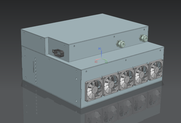
For the 2020-2021 season, the team decided to create a new battery pack for increased power density, increased safety, and increased power output. This is a multi-displinary project between the electrical and mechanical engineers on the team. I was responsible for designing the HV system inside of the battery which included sourcing the cells, sourcing HV components, and communicating with the mechanical designers in charge of the battery box.
Cell Selection

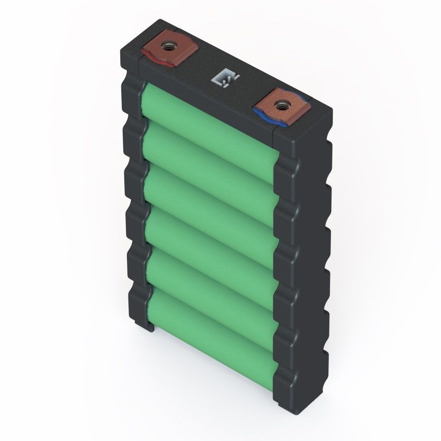
The requirements for this project were simple: increased power density with increased safety. For this reason, we decided to use a cell designed by Energus Power Solutions. These cells are extremely safe compared to prismatic pouch type configurations, as the only conductive parts of the cell are the 2 copper tabs on the top. The cells also come together into a 16 cell module very easily. For power density the cells contain 6 VTC6 18650 cells designed by Sony. Each cell can output 180A continuous, and 270A for 10 seconds. This gives us over 60kW of power in a 18.5" x 12.5" small area.
Design

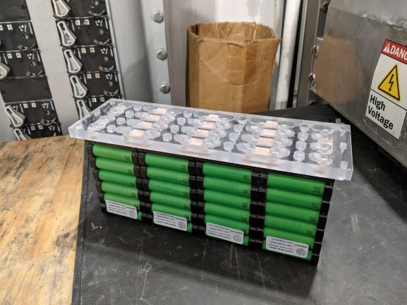
Due to the BMS's constraint of sensing 16 cells per BMS, a module can only include 16 cells. Relaying this with the mechanical engineers, we decided to do a 4x4 configuration as shown above in an assembled module. For structural stability, the modules are bolted into a plate that recesses the busbars and isolates them from the other busbars. In order to comply with our frame, we decided on 5 modules which gets us our voltage of 336V.
HV Components

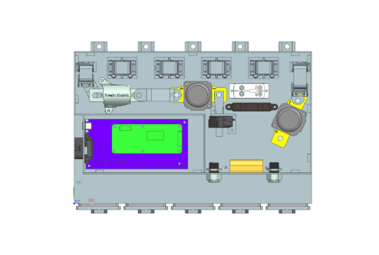
Knowing our max voltage of 336V and max current of 180A (270A for 10 sec) we decided on a 200A fast-acting main pack fuse. This is so that we can continuously pull 180A with no issue, but if we have a short circuit condition, the main pack fuse will blow before the parallel fusing off the cells, saving the battery pack. The other components inside of the battery include 3 contactors (HV relays), a precharge resistor, and a current sensor. The 2 large contactors selected support up to 350A current, with an interrupt of 800A. This may seem like overkill but the contactors support contactor state detection by means of a secondary coil that behaves like the main coil, letting you sense the state of the current carrying coil. The precharge contactor is smaller however, and rated for 50A. This is because the precharge circuit introduces a resistor of 1.5 kOhms on the positive rail, acting as a current limiting resistor. This is to prevent large inrush current due to connecting a capactive load.